Showing posts with label signal regeneration. Show all posts

Thursday, May 26, 2011

Talking About Regeneration

You probably realize that there is a distance limitation to sending signals through wires, fiber strands or wirelessly. Your USB and Ethernet cables can be just so long. Yet, we easily communicate worldwide on the Internet and through private networks. How’s that possible?

Signals do deteriorate as they travel. The trick is to boost them from time to time and recreate the original waveform. Analog phone lines use passive equalizer components, capacitors and coils, to compensate for the reactance in the wires that causes the voice signals to sound muffled before they get to the central office. Over longer distances, linear amplifiers boost signals that lose amplitude due to the resistance in the wiring.

There’s one small problem with simply amplifying a signal to bring it back to its original voltage. Amplifiers amplify everything. That includes the signal we want, but it also includes any noise that is picked up along the way. There’s lots of noise that leaks into the wiring. Twisting the pairs of copper wire helps cancel out external fields, but you still get small amounts of power line hum, crackles from thunderstorms, and crosstalk from other wires in the bundle. You boost the faded signal, but you boost the noise by the same amount reducing the ratio of signal to noise on the line. The longer the path, the noisier your signal gets at the end.

Digital transmission offers the opportunity to get around the deteriorating signal to noise problem. Digital signals have only two states, 1 and 0. These can be low and high currents, different polarity voltages or the presence or absence of a light pulse. It doesn’t matter as long as there is a way to tell the difference between the ones and the zeros. If so, you can recreate the original signal and throw out the noise completely.

Here’s a simple example. In the days of the telegraph, the Morse code dots and dashes could only be sent so far using the wires and batteries of the day. One solution is to have telegraph stations with live operators along the line between cities. The first station would send the message to the second, where it would be transcribed and then resent to the next station in line. Because the signal was regenerated completely, it would be exactly the same leaving the second station as it was leaving the first.

Telegraph repeater. Not quite fast enough for T1 lines, but this is how it started...


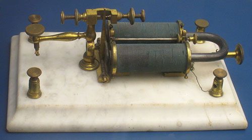
Well, in theory anyway. Any mistakes would show up as noise in the signal that couldn’t be removed. Besides being slow and potentially error-prone, this method is laborious. An automatic process is to have a telegraph receiver (sounder) connected to a key and re-transmit everything it receives. This is the familiar electrical relay. It is also a regenerative repeater. The relay repeats everything it receives and regenerates the signal back to its original form.

Sound old-timey? We still use this process for T1 lines. No, there are no Morse code keys in those telephone boxes. It’s all solid state electronics these days. The similarity between Morse code and T1 digital transmission is that they both use binary signals. The T1 line is running at about 1.5 Mbps, a bit fast for telegraphers but no problem for a solid state regenerator. The shape of the signal at the input has been distorted by electrical characteristics of the line and attenuation over distance. It has also picked up noise.

The regenerative repeater determines whether each pulse is a one or a zero and then recreates the string of pulses in the T1 signal at exactly the specified voltage level and waveform of a “perfect” T1 signal. You can’t tell the difference of a T1 signal leaving the telco office and one leaving a regenerative repeater. These repeaters can be placed every 6,000 ft to regenerate the signal back to spec. Five or ten miles out, it looks as good as it did at the central office.

The availability of simple, inexpensive regenerative repeater cards is what makes T1 service so universally available. It doesn’t matter if your business is located downtown or on a farm in the middle of nowhere. If you can get telephone service, you can probably get T1 service. T1 takes two pair of phone wires, one for upload and one for download. Other than that, regular multi-pair telephone cable is all that is required. If no T1 service has ever been installed for miles around, the provider may have to do some construction to install those regenerative repeaters to get the signal to your location.

Are you interested in getting T1 or higher speed line service for your business? It may be less expensive than you think and higher bandwidths are becoming more available. Get pricing and availability for T1 and other line services now and check out your options.

Click to check pricing and features or get support from a Telarus product specialist.


Note: Photo of telegraph repeater courtesy of Daderot on Wikimedia Commons


Follow Telexplainer on Twitter

Tuesday, January 25, 2011

Ethernet over Copper vs Bonded T1

T1 lines have been the gold standard for small and medium business connectivity. Their popularity has grown as pricing has plunged in recent years. Now there’s a newer technology service that gives you even more bandwidth for less money and is even easier to interface. That service is Ethernet over Copper.

Compare Ethernet over Copper to Bonded T1 lines for price and availability. Click to inquire.Ethernet over Copper, or EoC, leverages one of the primary attributes of T1 lines. That’s their ability to be provisioned over ordinary twisted pair telephone wiring. A T1 lines comes into your facility in the same bundle of installed telephone wire that brings in multi-line telephone service. Because it is ordinary telco wire, most every business location in the country is already wired for service and enabled for T1.

T1 lines use two twisted pair versus one pair for an analog telephone line. One pair is used for the upstream connection. The other is used for the downstream connection. This gives you 1.5 Mbps in both directions at the same time, also called full duplex operation. T1 line prices have come down to several hundred dollars per month, although that number varies with location.

For about the same money you can get Ethernet over Copper bandwidth. But your Ethernet link will be running at 3 Mbps rather than 1.5 Mbps. Why the difference? It’s a matter of more efficient modulation technology. T1 was designed by the phone companies right after WWII to transport telephone calls digitally. Thus, it was designed as a synchronized system subdivided into 24 precise channels. It’s a great match for loading phone lines onto a digital trunk, but bears no resemblance to today’s network protocols. Ethernet is based on packets, not channels, and doesn’t need the T1 system for transport. In fact, it takes a protocol conversion to go back and forth from T1 to Ethernet.

T1 lines can compete with Ethernet over Copper by using more lines to increase bandwidth. Add another 2 pair for an additional T1 line and you can double your bandwidth from 1.5 Mbps to 3 Mbps. The process used to couple multiple T1 lines to create one effectively larger line is called bonding. As you might expect, Ethernet over Copper lines can also be bonded to create a larger bandwidth connection. T1 line bonding is practical up to 10 or 12 Mbps. EoC bonding can deliver bandwidths as high as 100 Mbps over very short distances. Standard Ethernet network speed of 10 Mbps is readily available. You can also get 15 or 20 Mbps service without too much trouble. Once bandwidth gets above 45 to 50 Mbps, it generally makes sense to move up to fiber optic connections.

The one rub with Ethernet over Copper technology is that it is distance limited. That’s why EoC is often called a Metro Ethernet service. You’ll find it readily available in major metropolitan areas, but not farther out in sparsely populated areas. EoC delivery is generally limited to a few miles from the central office where the termination equipment is installed. For higher bandwidths, it’s only a matter of blocks away from the nearest point of presence. Downtown that’s no concern because of the concentration of both users and service provider facilities.

T1, on the other hand, has no distance limitation. It was designed from the beginning to have regenerators placed every mile or so in the line to restore the signal to a perfect wave shape. Longer spans require more engineering and construction effort, so cost goes up. Even so, you can get T1 service from coast to coast if you like. Actually, the T1 line is only carried by copper to the nearest telco central office. From there it rides on a fiber optic network to the central office nearest the far location and is then delivered on copper wiring.

Business bandwidth demands are increasing faster than fiber is being trenched to every business. That doesn’t mean you are stuck with a basic 1.5 Mbps of service when you really need 10 or 20 Mbps. Find out what’s available for your business location and compare prices for Ethernet over Copper vs Bonded T1 services now.

Click to check pricing and features or get support from a Telarus product specialist.


Follow Telexplainer on Twitter